Traditional IGBTs with high gate voltage losses carry the risk of short-circuit! Firstack 1FHD0440 features revolutionary driver technology that eliminates the risks associated with high gate voltage, significantly reduces power transmission losses, and helps power grid projects save tens of millions in electricity costs annually—delivering dual upgrades in safety and efficiency.
1. Introduction
As a key component of the converter valve—the core equipment of flexible DC transmission systems—IGBTs play a crucial role. Therefore, driver technology that ensures their stable, reliable, and low-loss operation is of particular importance for flexible DC converter valves. Currently, in hybrid full- and half-bridge flexible DC transmission converter systems using traditional IGBT drivers, losses are around 0.8%, indicating limited loss reduction and a relatively high loss rate. Taking a 10 GW FDC project for inter-regional power transmission—which delivers 45 billion kWh of electricity annually—as an example, the annual losses in the converter valve caused by traditional IGBT driver technology exceed 360 million kWh. At a rate of 0.33 yuan per kWh, this amounts to a loss of over 118.8 million yuan, directly impacting economic efficiency.
Firstack proudly introduces the 1FHD0440, which effectively helps customers reduce losses and improve efficiency by increasing the gate voltage, while simultaneously addressing the risk of IGBT short-circuit failure caused by high gate voltages. This article will focus on these two aspects.
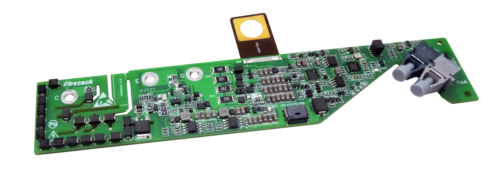
1FHD0440
Advantages: | Applications: |
|
|
|
|
|
|
2. Reducing On-State Losses by Increasing Gate Voltage
IGBT losses primarily consist of on-state losses and switching losses. Since VSC-HVDC systems employ a hybrid full-half-bridge configuration with multiple steps in the output waveform, even very low switching frequencies can result in excellent waveform quality with extremely low harmonic content. In VSC-HVDC applications, the switching frequency is typically only 100–300 Hz—about one-tenth that of conventional converters—resulting in low switching losses. Therefore, reducing IGBT conduction losses becomes a top priority. The most effective approach is to increase the IGBT’s gate voltage to lower the VCE saturation voltage drop, thereby reducing conduction losses.
Taking the IGBT module (FZ1200R45HL3_S7) as an example, the relationships between IC, VCE, and VGE are as follows, with Tvj = @150°C:
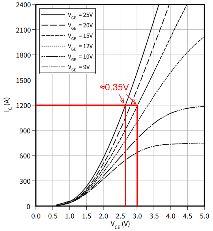
At Tvj = 150°C and IC = 1200 A, when the gate voltage is increased from 15 V to 25 V, the VCE on-state voltage drop decreases from 3V to 2.65V—a reduction of approximately 0.35V. This results in a reduction of 420W in on-state power dissipation, achieving a reduction ratio of 12%.
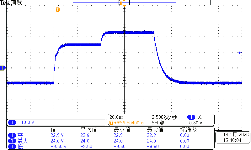
Therefore, after the IGBT is fully turned on, the 1FHD0440 increases the gate voltage from 15 V to 25 V. Its normal gate waveform is shown in the figure below:
3. Risk of Short-Circuit Failure Due to High Gate Voltage
Increasing the gate voltage can reduce the on-state losses of an IGBT, but it also introduces other risks. The figure below shows the relationship between gate voltage, short-circuit current, and maximum short-circuit duration for a 1200V IGBT module, which helps us understand the risk of short-circuit failure associated with high gate voltage.
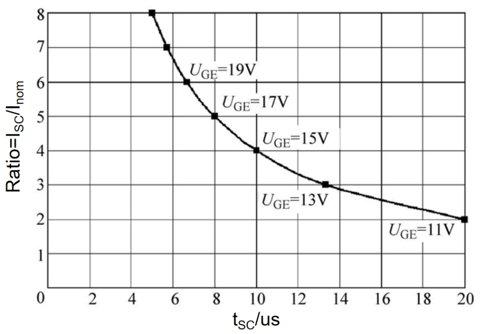
As shown in the figure above, as the gate voltage increases, the module’s short-circuit current increases. Since the short-circuit energy that an IGBT chip can withstand is fixed, its short-circuit withstand time decreases accordingly, reaching a minimum of approximately 4 μs. Therefore, when the IGBT gate voltage is raised to 25 V, conventional short-circuit protection based on the short-circuit desaturation principle is no longer sufficient, and the risk of short-circuit failure in the module is extremely high.
4. High-Gate-Voltage Short-Circuit Protection Technology
Firstack leverages the fast response time of di/dt short-circuit protection, which, when combined with traditional VCE short-circuit protection, ensures the safe turn-off of IGBTs. We verified this by simulating Type I and Type II short-circuit conditions; the test conditions and short-circuit protection waveforms are shown below:
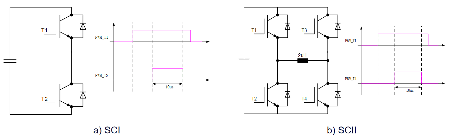
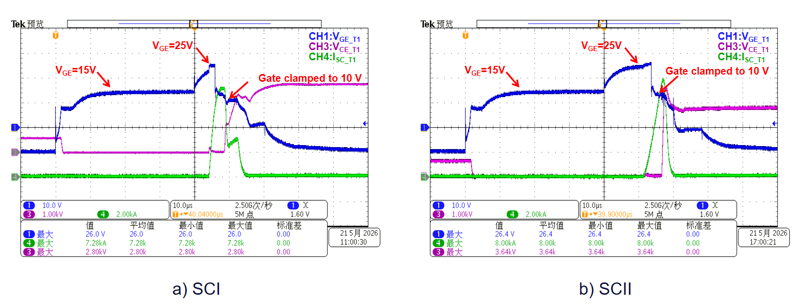
As shown in the Class I and Class II short-circuit protection waveforms in the figure above, after the 1FHD0440 rapidly identifies a short-circuit fault using its di/dt short-circuit protection function, it actively adjusts the gate voltage so that the VCE short-circuit protection function can ultimately confirm the short-circuit fault and execute a soft shutdown, enabling the IGBT to turn off safely and reliably.
5. Applications
The 1FHD0440 can be used not only in applications such as HVDC and STATCOM, but also in grid-level or data center solid-state circuit breaker (SSCB) applications. In SSCB applications, the device remains in a continuously conductive state during normal operation and is activated only when a fault occurs to isolate the fault. Therefore, increasing the gate voltage and reducing the on-state voltage drop can help significantly reduce losses in such applications, which is of great engineering significance.

For more details, please refer to: 1FHD0440