 English
If you drive lower-power stages and want to own the whole board, a gate driver IC (integrated circuit) is usually enough. If you drive high-power IGBT (insulated-gate bipolar transistor) or SiC (silicon carbide) modules and need isolation, protection and repeatable production on a tight schedule, a gate driver core is the safer pick.
Most engineers start by searching for gate driver ICs, because the chip is the obvious part to select. In high-power designs, however, the chip is only one piece of the job. This guide shows where the line sits, using datasheet numbers.
What Is the Difference Between a Gate Driver IC and a Gate Driver Core?
A gate driver IC is one chip, while a gate driver core is a finished driver board built around that function. The real difference is how much circuitry you add yourself.
How Does a Gate Driver IC Work in a Discrete Design?
A driver IC turns a logic-level PWM (pulse-width modulation) signal into gate pulses, and isolated versions add protection. For example, Infineon's 1ED332x family offers +6 A/−8.5 A typical peak current, DESAT (desaturation) detection, soft turn-off and an active Miller clamp. NXP's GD3160 integrates a 15 A gate driver with signal isolation up to 8 kV and targets xEV traction inverters.
Even so, each chip still needs company. You add an isolated gate supply, gate resistors, DESAT sensing parts and a disciplined layout.
What Does a Gate Driver Core Add on Top?
A gate driver core packages those surrounding parts into one module. Firstack’s 2FHC0435 shows what that looks like in practice. It is a dual-channel core rated at 4 W per channel at 85 °C ambient (6 W at 70 °C), with ±35 A gate peak current and an on-board isolation transformer. It runs from a 15 V supply and outputs +15 V/−8 V gate drive.
How Do They Compare Side by Side?
The two approaches differ most in drive current, isolation effort and who owns the protection tuning.
| Factor | Gate driver IC | Gate driver core (2FHC0435 datasheet) |
| Drive current | 6 A to 15 A typical on the ICs above; external buffer beyond that | ±35 A peak, two channels |
| Isolation | Signal isolation in the chip; gate power supply is your design | 5,000 VRMS primary-to-secondary and 4,000 VRMS secondary-to-secondary test voltage |
| Short-circuit protection | DESAT and soft-off built in; you tune thresholds | VCE threshold 10.1 V (Rthx = 68 kΩ), 4 µs response, 4.16 µs soft shut-down |
| Off-state control | Active Miller clamp on many ICs | −8 V typical turn-off gate voltage |
| EMI (electromagnetic interference) | Depends on your layout and supply | Digital design; Firstack states lower EMI than analog drivers |
| Development effort | Schematic, layout, tuning | Datasheet calls peripheral circuits simple |
| BOM (bill of materials) | Many line items around the chip | Fewer parts on your BOM, because the module is one purchased item |
Why Do Short-Circuit and Miller-Clamp Needs Differ Between IGBT and SiC?
SiC tolerates a short circuit for far less time than silicon IGBTs. Fuji Electric reports typical IGBT module short-circuit withstand times of 5 to 10 µs. Analog Devices notes that SiC MOSFETs generally cannot survive beyond roughly 1 to 3 µs. Therefore, onsemi advises that desaturation circuits built for IGBTs must be optimized for SiC MOSFETs.
Parasitic turn-on adds a second concern. Negative gate voltage is typically used above about 100 A nominal current, while an active Miller clamp is the lower-cost alternative below that. STMicroelectronics adds that a clamp cannot replace negative drive in very high-power designs, because the clamp path has parasitic inductance.
How Much Design and Validation Work Does Each Approach Require?
A driver IC leaves most of the design and validation work with your team, while a core moves much of it to the supplier. The gap shows up in the schedule, not in the schematic.
What Must You Design Around a Gate Driver IC?
1. Build an isolated gate supply with enough creepage and clearance.
2. Size gate resistors and, if needed, an external buffer.
3. Tune the DESAT threshold and blanking time to the module's short-circuit withstand time.
4. Lay out the board for high dV/dt, keeping the gate loop short.
5. Run double-pulse and short-circuit tests, then iterate.
Where Does Time Go During Validation?
Most time goes into the short-circuit tests, because one wrong blanking value can destroy a module. A gate driver core narrows that search. On the 2FHC0435, the 4 µs response time is measured from fault to the start of soft shut-down, with Rax = 120 kΩ and Cax = 0 pF. The soft shut-down itself then takes 4.16 µs.
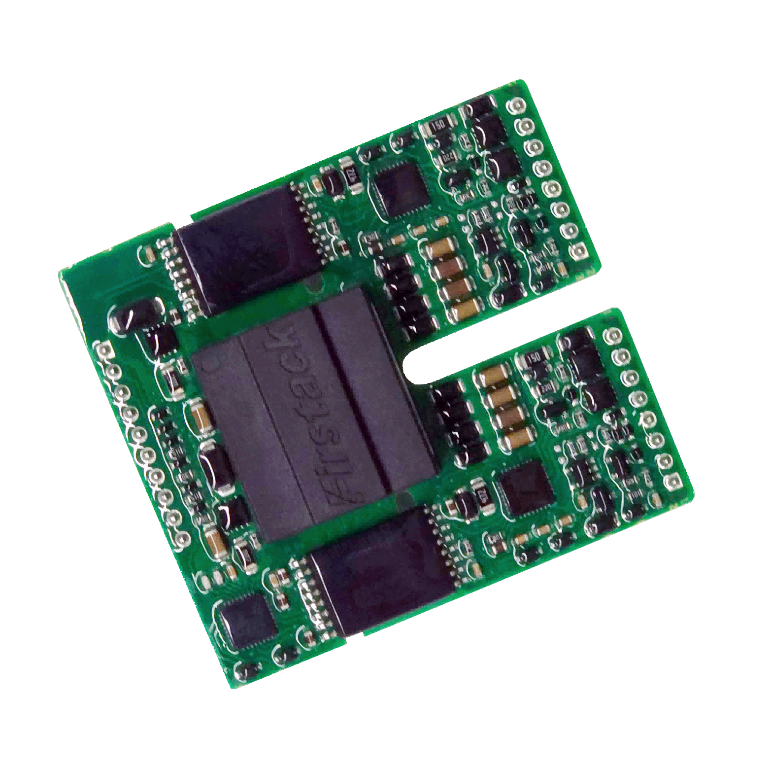
You still validate in your own inverter. Compare both figures with your module's datasheet withstand time before you commit.
The datasheet also lists status outputs SO1 and SO2 that go low on a fault, plus an 80 ms secondary-side fault blocking time and a 10 ms fault return time after a short circuit. As a result, your controller receives a clear fault signal without extra monitoring circuitry.
When Should You Choose a Gate Driver IC or a Gate Driver Core?
Choose by power level, module package and production plan.
| Situation | Better fit |
| Board-level design, lower current, your team owns layout | Gate driver IC |
| Automotive functional safety (the GD3160 is ASIL D certified, per NXP) | Gate driver IC |
| High-power module at 1700 V or above, small design team | Gate driver core |
| Repeatable production without re-tuning each build | Gate driver core |
For example, a team building a compact drive around one 1,200 V device can reasonably use a driver IC. In contrast, a team driving a 1700 V IGBT module in an energy storage inverter must design isolation and protection around the chip. A gate driver core supplies much of that circuitry on one board.
Switching frequency matters too. The 2FHC0435 supports applications up to 30 kHz, while NXP lists PWM operation up to 100 kHz for the GD3160. Therefore, designs that switch at very high frequency may still favor a chip.
Where Does the Firstack Gate Driver Core Fit?
Firstack fits the high-power end of this decision. Firstack Technology Co., Ltd. (Hangzhou, China) describes itself as an expert in power system reliability. Its homepage lists a programmable ASIC for SiC devices and validation at device, board, module and system level.
The Firstack Gate Driver Core range covers both switch types, as the table below shows.
| Part | Rating | Switch | Max breakdown voltage |
| 2FHC0240 | 2 W / 40 A | SiC | 2300 V |
| 2FHC0215C / 2FHC0215xV | 2 W / 15 A | IGBT | 1700 V |
| 2FHC0435 | 4 W / 35 A | IGBT | 1700 V |
| 2FHC0660 | 6 W / 60 A | IGBT | 3300 V |
Which Firstack Core Matches Your Switch and Voltage Class?
Match the core to the switch first, then to the voltage. The 2FHC0240 targets SiC with Miller clamp, and the 2FHC0660 covers 3300 V IGBT designs. The 2FHC0435 supports up to 1700 V IGBT modules at up to 30 kHz, in direct mode or half-bridge mode. Firstack lists its target uses as motor drives and energy storage.
Conclusion
A gate driver IC wins when you want control and own the validation. A gate driver core wins when the module is large, the voltage is high and the schedule is short. Both can serve IGBT gate drivers well, so the deciding factor is who carries the isolation, protection and testing work.
To compare options, start with your module's short-circuit withstand time, then check each driver IC or core against it.
For a 1700 V IGBT module in a motor drive or energy storage inverter, that comparison usually points to a gate driver core.
Sources
• Firstack homepage. https://www.firstack.com/
• Firstack Gate Driver Core product page. https://www.firstack.com/products/gate-drivers/gate-driver-core/
• Firstack, 2FHC0435 Data Sheet, 2024-07-24 (supplied PDF, www.firstack.com).
• Infineon EiceDRIVER 1ED332x evaluation board description (Würth Elektronik component reference). https://we-online.com/en/components/icref/infineon-technologies/1ED332x-EVAL-1ED3321MC12N-Half-Bridge-Isolated-
• NXP GD3160 Advanced Gate Drivers (Mouser product page). https://www.mouser.in/new/nxp-semiconductors/nxp-gd3160-drivers/
• NXP GD3160 data sheet. https://nxp.com/docs/en/data-sheet/GD3160.pdf
• Fuji Electric, Understanding Short Circuit Withstand Time (SCWT) in IGBTs. https://americas.fujielectric.com/understanding-short-circuit-withstand-time-scwt-in-igbts/
• Analog Devices, Advanced Overcurrent Detection with Digital Controllable Blanking Time for Fast SiC-Switch Protection, PCIM Europe 2022. https://www.vde-verlag.de/proceedings-de/565822222.html
• Onsemi, Application Note AND90337. https://www.onsemi.com/download/application-notes/pdf/and90337-d.pdf
• Control Engineering, Mitigating parasitic turn-on effect in IGBT-output drives. https://www.controleng.com/?p=76019
• STMicroelectronics, Application Note AN2123 (TD351 advanced IGBT driver). https://www.st.com.cn/resource/en/application_note/an2123-td351-advanced-igbt-driver-principles-of-operation-and-application-stmicroelectronics.pdf

