 English
Power electronic systems rely on semiconductor devices to control how electrical energy is converted, regulated, and delivered. Among the key components used in industrial converters, motor drives, renewable energy systems, and power transmission equipment, the insulated-gate bipolar transistor (IGBT) remains an important switching device. However, an IGBT cannot operate reliably through a control signal alone. A properly designed IGBT gate driver provides the electrical conditions needed for controlled switching, protection, and stable system performance.
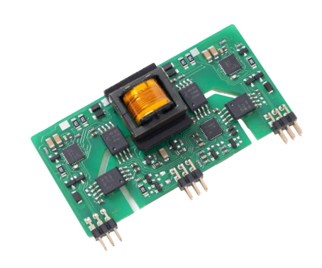
What Is an IGBT and How Does It Work?
An IGBT combines the voltage-controlled gate structure associated with a metal-oxide-semiconductor field-effect transistor (MOSFET) with the bipolar conduction characteristics of a bipolar junction transistor. This combination allows it to handle relatively high voltages and currents while maintaining practical gate-control requirements.
During operation, applying a suitable gate-emitter voltage turns the device on, allowing current to flow between the collector and emitter. Removing or reducing the gate drive turns it off, although the switching process depends on the device characteristics and circuit conditions. IGBTs are widely used in applications where efficient control of substantial electrical power is essential.
Typical applications include variable-frequency motor drives, photovoltaic inverters, wind power converters, traction systems, industrial welding equipment, and high-power uninterruptible power supplies. Device selection depends on factors such as blocking voltage, current rating, switching frequency, conduction losses, thermal performance, and short-circuit withstand capability.
Why an IGBT Needs a Dedicated Gate Driver
A controller typically generates low-voltage logic signals, whereas the IGBT gate requires a suitable voltage level and enough current to charge and discharge its gate capacitance. Connecting the controller directly to the power device generally cannot provide the drive capability, electrical separation, and protection required in practical high-power circuits.
A dedicated IGBT gate driver bridges this gap. It translates control commands into gate signals with appropriate voltage levels, switching timing, and current capability. It must also manage the electrical relationship between the low-voltage control circuit and the power stage.
The driver influences switching speed, power losses, electromagnetic interference (EMI), and operational reliability. An unsuitable design may cause excessive switching losses, unwanted turn-on, voltage overshoot, or device damage. For this reason, we should treat gate-drive design as an integral part of power-stage engineering rather than a secondary component choice.
Key Functions of an IGBT Gate Driver
A well-matched IGBT gate driver performs several functions that support reliable switching and help protect the power semiconductor.
Gate voltage and current control: The driver supplies the required gate-emitter voltage and sources or sinks current to control turn-on and turn-off transitions. Correct drive strength helps balance switching losses against voltage overshoot and EMI.
Electrical isolation: Many high-voltage designs require galvanic isolation between control electronics and the power stage. The isolation system must meet the application’s working-voltage, transient, and safety requirements.
Fault protection: Depending on the design, protection features may include undervoltage lockout (UVLO), desaturation detection, short-circuit protection, and fault signaling. These functions can help the system respond when operating conditions become abnormal.
Switching coordination: Half-bridge and other multi-switch circuits require suitable timing and dead time to prevent simultaneous conduction. Propagation delay and channel matching should be considered when selecting and configuring the driver.
Not every application needs identical features. We should evaluate the device datasheet, circuit topology, operating conditions, and system-level safety requirements before finalizing the driver specification.
How to Select a Suitable Driver for Your Application
The selection process should begin with the semiconductor module rather than a generic driver rating. Review the recommended gate voltage, maximum gate-emitter voltage, total gate charge, switching frequency, and required peak source and sink currents. Then assess the expected switching losses and thermal limits under actual operating conditions.
Isolation requirements deserve equal attention. Check the driver’s isolation rating, common-mode transient immunity, creepage and clearance, and compatibility with the system’s insulation coordination. A high isolation rating alone does not guarantee reliable operation if PCB layout, grounding, or signal routing is inadequate.
Protection requirements should reflect the application’s risk profile. Industrial motor drives, renewable energy converters, and railway traction equipment may face different fault conditions, thermal environments, and maintenance constraints. Engineers should also consider interface compatibility, operating temperature, mechanical dimensions, and ease of system integration.
Finally, validate the complete circuit through testing. Measure gate waveforms, switching transitions, overshoot, ringing, temperature rise, and fault response. Testing across the intended voltage, load, and temperature range helps reveal issues that component datasheets alone cannot predict.
How Firstack Supports Power Electronics Development
At Firstack, we specialize in the research, development, and sales of power semiconductor drivers, power stacks, and testing equipment,and have more than 150 intellectual property rights.
Our solutions serve strategically important industries, including renewable energy, rail, power transmission, and motor drives. These applications require careful coordination between control signals, switching devices, protection functions, and system-level operating requirements.
When evaluating driver solutions, we encourage engineers to consider the complete power-conversion system, including device compatibility, electrical interfaces, switching behavior, and testing needs. This approach helps establish a sound technical foundation before equipment enters full-scale operation.
Building Reliable Power Systems Through Proper Gate Drive Design
Reliable switching depends on more than the semiconductor itself. Appropriate gate voltage, sufficient drive current, isolation, protection, and timing coordination all contribute to effective power conversion. By matching the driver to the device and validating the complete circuit, engineers can reduce avoidable design risks and improve system reliability. At Firstack, we support power electronics development with driver technologies and testing capabilities designed for demanding industrial applications.

