1 Introduction of Optical Fiber Module
1.1 Optical Fiber Module
Key components within optical fiber communication systems, facilitate the conversion between electrical and optical signals. These modules are categorized as either transmitter or receiver types and are colour-coded for identification—grey denotes transmitter modules, while blue indicates receiver modules—serving as a foolproof measure. Presently, IGBT drivers predominantly utilize plastic optical modules and metal clip-on (ST) optical modules; the selection of appropriate optical fiber modules must be determined based on the specific application scenario.
1) Plastic Optical Fiber Modules
Plastic optical fiber module currently operates primarily at a wavelength of 650nm, employing LED technology with data rates ranging from 40Kbps to 50Mbps and utilizing plastic optical fiber (POF) for transmission distances between 10m and 110m. However, with the introduction of new products, plastic optical fiber module can now be compatible with plastic-clad silica (PCS) fiber, extending transmission distances up to 500m.
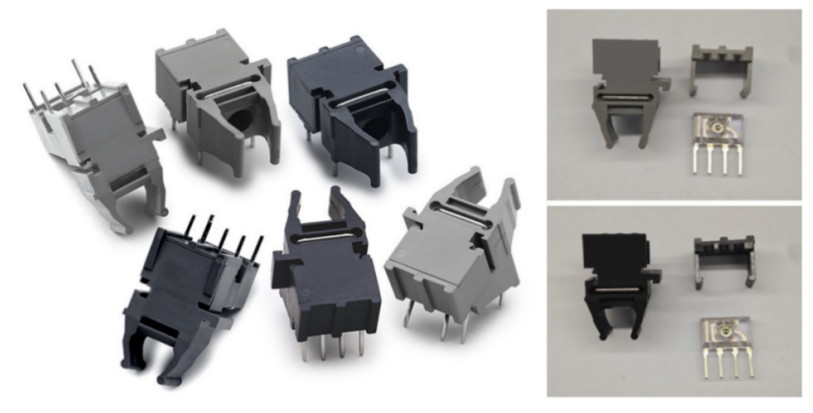
Fig.1: Plastic Optical Fiber Module and Internal Structure
Plastic optical modules typically come in three packaging forms: horizontal, vertical, and tilted at 30°. As shown in Fig.1, their internal structure is straightforward: the light-emitting diode or receiver chip is encapsulated in transparent material and assembled into the housing for use. Plastic optical modules typically feature a substantial numerical aperture (NA) of 0.5. The numerical aperture is a dimensionless quantity defining the maximum angular range within which light can be received or propagated by an optical fiber. Any incident light with an angle smaller than this maximum angle can be captured by the fiber and transmitted internally via total internal reflection. Its formula is as follows:
NA=0.5 corresponds to an angle of approximately 30°, which is exceptionally broad. This enables POF to receive the vast majority of light emitted by the LED, resulting in high coupling efficiency. This reduces the demands placed on the light source and simplifies the alignment precision required for connectors, thereby lowering overall system costs. However, the primary drawback of high NA is that the fiber receives light from numerous angles, with vastly differing path lengths within the core. This leads to pulse broadening at the output when a short optical pulse is input, due to the varying path lengths traversed by the light. This phenomenon, known as modal dispersion (readers may wish to research this concept further), severely limits the fiber's data rate and maximum transmission distance. Thus, plastic optical modules sacrifice data rates and distance to achieve exceptionally high light collection efficiency, more convenient connectivity, and lower system costs. This trade-off is precisely why they have secured a niche in specific markets such as automotive, industrial, and home appliances.
2) ST Optical Fiber Modules
ST optical fiber modules currently operate primarily at a wavelength of 850nm. The majority of products on the market still employ LED technology, though new models are gradually transitioning to VCSEL laser technology. Data rates range from 100Kbps to 50Mbps, utilizing glass fiber for transmission distances of up to 3km.
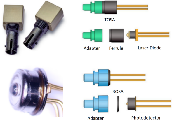
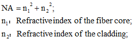
Fig.2 ST Optical Fiber Modules and Internal Structure
ST optical modules comprise distinct core components at their transmit and receive ends: the transmitter optical subassembly (TOSA) and the receiver optical subassembly (ROSA). The TOSA primarily comprises an adapter, a chip sleeve, and a laser (see the lower-left image in Fig.2). By adding an appropriate housing to its optical output end, it can form optical modules with various standard interfaces. Similarly, the ROSA functions in the same manner, though it lacks the chip sleeve present in the TOSA. Both lasers and detectors are sealed devices filled with inert gas and undergo hermeticity testing. Consequently, ST optical modules theoretically exhibit higher moisture sensitivity levels than plastic modules, potentially reaching MSL1. However, aside from select new components, most datasheets do not specify this information. As critical system components directly impacting signal transmission quality, optical modules must be stored and preserved according to datasheet requirements.
1.2 Optical Fiber
Optical fiber, known as light-conducting fiber, are filaments made of glass or plastic that transmit light through the principle of total internal reflection. Consequently, the refractive index n₁ of the fiber core is greater than that of the cladding n₂.
Optical fiber are categorized into single-mode fiber (SMF) and multi-mode fiber (MMF), primarily based on considerations of modal dispersion effects. Single-mode fiber typically employs highly directional laser light sources and transmits primarily a single mode of light, offering superior signal integrity and enabling transmission over distances of tens of km. The typical wavelengths for single-mode fiber are 1310nm and 1550nm. In contrast, multi-mode fiber usually employs LED light sources to transmit multiple modes of light. Due to dispersion effects, transmission is limited to medium-to-long distances of 1-3 km; plastic optical fiber may even be restricted to distances under 100m.
Fig.3 Single-Mode and Multi-Mode Optical Fiber Transmission
From Fig.3, we can clearly observe that the pulse signal transmitted via multi-mode fiber undergoes distortion after long-distance propagation, transforming from a tall, narrow pulse into a short, broad signal. Conversely, the pulse signal transmitted through single-mode fiber remains largely unaffected.
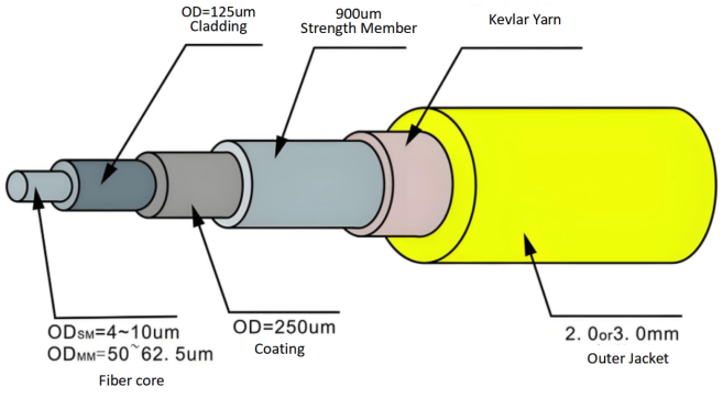
Fig.4 Overall Structure Diagram of the Optical Fiber
Fig.4 illustrates the overall structure of an optical fiber cable. The core diameters of single-mode and multi-mode fiber differ, with single-mode fiber featuring a smaller core diameter than multi-mode fiber. This is primarily to mitigate the effects of modal dispersion. The core diameter of single-mode fiber typically ranges from 4 to 10μm. whereas multi-mode fiber cores measure 50–62.5μm with cladding diameters of 125μm. Consequently, optical module specifications invariably specify compatible fiber types, such as 50/125μm or 60/125μm multi-mode fiber. Both the plastic optical modules and ST optical modules discussed herein employ multi-mode fiber.
2 Why Use Optical Fiber Module?
So, why do IGBT drivers require optical fiber module? Many IGBT drivers function perfectly well with flat cable assemblies alone – does adding optical modules not significantly increase costs?
In fact, one of the most critical functions of IGBT drivers in practical applications is achieving electrical isolation—both for power supply and signal transmission. This is because the high-voltage side of IGBTs typically operates at hundreds or even thousands of volts under high currents, while the low-voltage side (such as the controller) functions at mere 5V or even 3.3V levels. Without electrical isolation, high voltages from the main circuit could surge instantaneously into the controller, causing its destruction.
Current IGBT module ratings primarily cover 650V, 1200V, 1700V, 2300V, 3300V, 4500V, and 6500V. For IGBTs rated at 2300V and below, discrete components meeting isolation requirements are readily available on the market. However, IGBTs rated at 3300V and above typically employ optocoupler modules for isolation, primarily constrained by the devices' safety gap requirements and reliability considerations.
Table 1 Comparison of Isolation Technologies
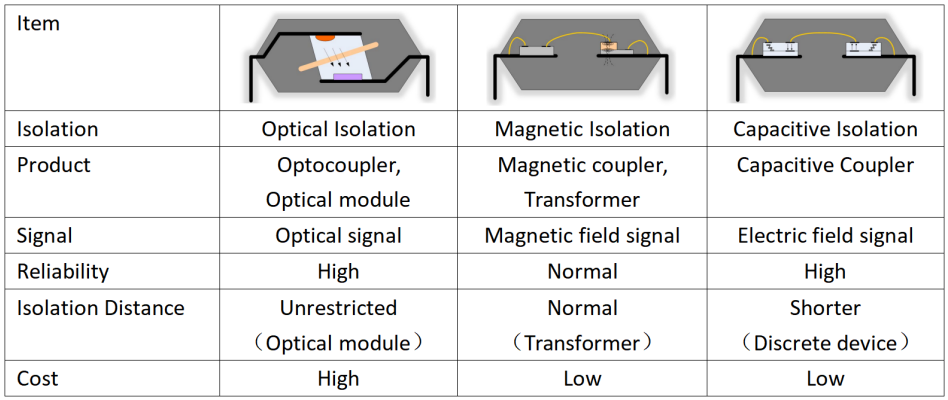
IGBTs rated below 2300V are typically employed in compact converters where the controller is situated relatively close to the inverter unit. Control signals are transmitted to the inverter via ribbon cables, with electrical isolation achieved through the use of isolating components in the driver section. Stable control signal transmission is ensured through proper EMC design. Currently, all three isolation methods for IGBT drivers are utilized in such applications, though there is a gradual shift away from optical isolation towards magnetic or capacitive isolation. IGBTs rated above 3300V are typically deployed in high-reliability scenarios, such as flexible DC transmission in power grids, traction converters for rail transit, and propulsion converters for marine vessels. These installations are often large-scale, with distances between controllers and inverter units spanning several metres or even tens of metres. Consequently, optical modules coupled with fiber optic cables have become the primary solution.
Within the rail transit sector, certain operational scenarios necessitate enhanced insulation, demanding drivers with greater electrical clearance and creepage distances. This requirement renders commercially available isolating components incapable of meeting safety-related distance specifications. However, human ingenuity knows no bounds. Why not directly encapsulate the optical module and fiber into a single device? Provided the structure permits, adjusting the fiber length can yield a component meeting safety standards. Thus emerged a novel device, colloquially termed the fiber optic coupler, professionally known as the High-Voltage Galvanic Insulation Link. The fiber optic isolator primarily consists of plastic optical module transceiver components paired with plastic optical fiber. It continues to utilize 620nm wavelength LED technology, achieving a maximum electrical clearance and creepage distance of 101.2mm, with a maximum operating voltage of 17kV.
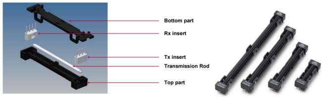
Fig.5 Optical fiber Coupler Structure
3 Selection of Optical Modules
Optical modules possess several key parameters that directly influence signal transmission distance and reliability, namely data rate, transmit optical power, and receive optical power.
1) Data Rate: Refers to the volume of valid data successfully transmitted from the source to the destination per unit time, measured in Mbps.
2) Transmit Optical Power: Denotes the optical power output from the transmitter's light source under normal operating conditions, measured in dBm.
3) Receive Optical Power: Represents the average optical power range receivable by the receiver under specified bit error rate conditions, measured in dBm. The upper limit corresponds to overload optical power, while the lower limit denotes the maximum receiver sensitivity.
The PWM signals transmitted by high-voltage IGBT drivers typically operate at frequencies below 5kHz, rendering a data rate of 5Mbps generally sufficient. For communication applications, however, rates of 50Mbps or higher may be selected. In terms of cost, plastic optical modules are comparatively inexpensive, whereas ST optical modules are significantly more expensive, often constituting the majority of a board's total cost. Plastic optical modules are primarily deployed in automotive, industrial, and home appliance sectors, whilst ST modules predominantly serve high-reliability applications such as marine propulsion and power transmission/distribution networks.
The selection of transmit and receive optical power directly influences signal transmission distance. Optical modules require appropriate drive current and compatible fiber to meet field application requirements. The transmission distance calculation formula is as follows:
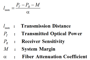
As the selected drive current must account for optical attenuation rather than adhering to the specification's recommended value, the corresponding output optical power must be determined using the forward conduction current and normalized output optical power curve provided in the specification. The maximum receiver sensitivity can be obtained from the photodetector performance parameters in the matched receiver module's specification. The system margin M is typically around 2dB. The attenuation coefficients of different fiber types also vary. For the 850nm wavelength band: - 50/125μm multi-mode fiber α is typically taken as ≤(3~4)dB/km; - 62.5/125μm multi-mode fiber α is typically taken as ≤(2.7~3.5)dB/km; - 200μm multi-mode fiber α is typically taken as ≤6dB/km.
Assuming the transmit optical module operates at a drive current of 30mA, with a typical transmit optical power of -14dBm at 60mA, with its forward conduction current versus normalized output optical power curve shown in Figure 6. Given that the maximum reception sensitivity of the receiving optical module is -35 dBm and the attenuation of 62.5/125μm multi-mode fiber is 2.8 dB/km, what transmission distance can be achieved?
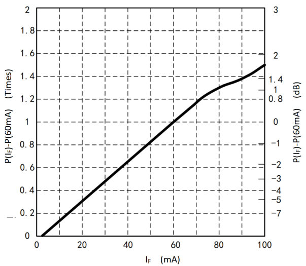
Fig.6 Forward conduction current versus normalized output optical power curve
As shown in the figure above, the optical output power of this transmitter module at 30mA is half that at 60mA, representing a change of -3dB, equivalent to -17dBm. Its transmission distance:
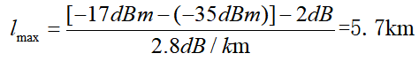
Note that in the formula, dBm represents an ‘absolute quantity’ concept, while dB denotes a ‘relative quantity’ concept, and the two can be added or subtracted. Therefore, based on the transmission distance, data rate, and cost of the optical fiber module, we can select the appropriate optical module for the required application scenario.
4 Precautions for Optical Fiber Module
When evaluating optical modules, most engineers focus solely on whether their electrical performance meets requirements, often overlooking critical manufacturing details during usage. This oversight frequently results in unstable field performance of the developed products.
4.1 Foreign Particle Removal
Throughout the optical link, the tolerance for contaminants such as dust is virtually zero when employing optical modules and fiber. Airborne dust particles can be as large as the fiber core diameter, absorbing significant light while also scratching the fiber end-face. This impact is particularly pronounced when ST optical modules are used with 50/125μm or 60/125μm multi-mode fiber, exhibiting greater severity than with plastic optical fiber modules. Contaminants represent the primary cause of component scratches and high optical loss throughout the optical chain. Consequently, optical modules typically undergo foreign particle removal during manufacturing and are supplied with a dust cap.
Foreign matter removal generally employs compressed air dust removal cans, using inert gases such as nitrogen to repeatedly spray the entire sleeve for dust removal; alternatively, a dedicated anti-static swab dipped in an appropriate cleaning agent may be extended to the bottom of the sleeve for cleaning, with one swab corresponding to one optical module. During user operation, except for necessary testing and ageing processes, it is imperative to ensure the dust cap remains attached to the optical module. It is imperative that the composition of any cleaning gas or solvent selected is verified with the supplier to prevent potential damage to the optical module itself.
4.2 fiber Optic Bending
When handling fiber optic cables, we often coil excess lengths into several loops for tidiness. Whilst this appears to organize the system cabling, this seemingly harmless practice can actually cause unstable signal transmission.
Here we must address fiber optic loss. Due to material impurities and imperfect connection methods, light intensity inevitably attenuates. Firstly, the fiber material and inherent impurities absorb light energy, converting part of it into heat. Secondly, achieving absolute material purity is impossible; insufficient purity leads to non-uniform refractive indices, causing scattering. Furthermore, fiber structures cannot be perfectly uniform, and connections, bends, and other factors all contribute to loss.
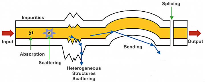
Fig.7 Optical Fiber Loss Form
In everyday applications, coiling optical fiber into several loops results in the micro-bend or macro-bend loss depicted in the diagram above. This loss fundamentally arises when the bending position fails to satisfy the conditions for total internal reflection, causing partial light leakage beyond the core and cladding. A sharp bend with a 5mm radius incurs a loss equivalent to enabling the light to travel an additional 50km. Therefore, during static installation, strict adherence to minimum bending radius requirements is essential. Specifically, the bending radius of the optical fiber cable must not be less than ten times the diameter of the outer sheath. For example, with a cable diameter of 2.2mm, the bending radius must be ≥22mm. Specification sheets for optical fiber typically provide detailed requirements. When assessing system transmission intensity, actual measurements must be taken according to the precise installation process and route to avoid significant variations in light intensity caused by macro-bend loss.
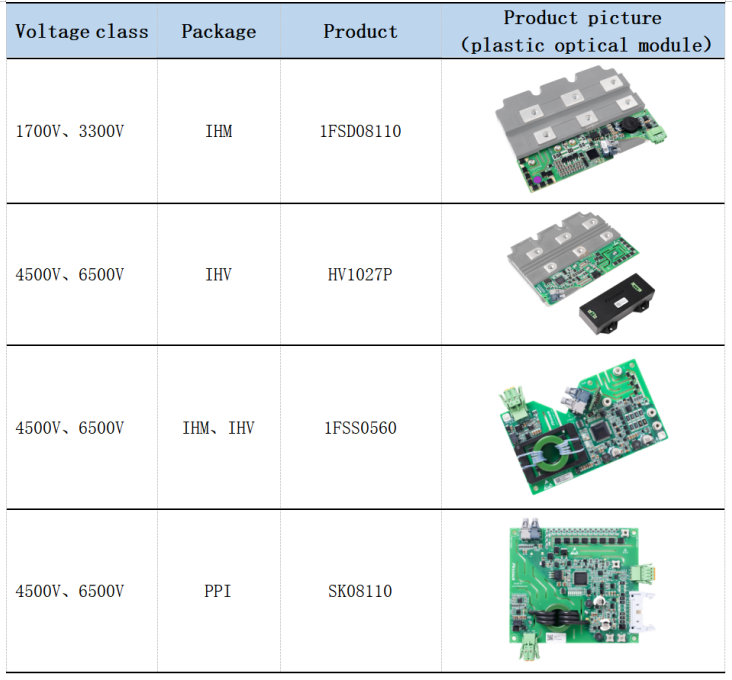
5 IGBT Driver Products Based on Optical Modules
In high-voltage, high-power converter applications such as rail transit converters, MW-class high-power inverters, MW-class marine propulsion systems, high-voltage static voltage regulators (SVG), and HVDC converter valves, IGBT modules rated at 3300V, 4500V, and 6500V are employed, necessitating the use of IGBT driver products based on optical modules.
Firstack possesses over a decade of application experience in optical module-based IGBT driver products, with cumulative shipments exceeding 200,000 units. We welcome your enquiries and orders at any time.
For ST optical module driver products, please consult Firstack sales for technical support.