In the previous article, we discussed the critical role of Miller clamping in SiC drivers. This article will delve deeper, analyzing the short-circuit protection mechanisms in SiC drivers and outlining the core considerations for building a test platform. While the theory and design of short-circuit protection are well-established, its true value lies in the reliability of its practical application. SiC devices feature faster switching speeds and higher short-circuit currents, posing stringent challenges to the speed and robustness of protection responses. Hope this article provides practical guidance and assistance for validating the short-circuit protection functionality of SiC drivers.
Short-Circuit Protection Step 1: Detection
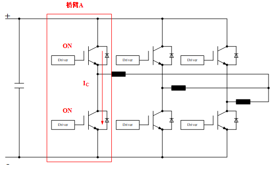
The primary step in implementing short-circuit protection is the accurate and rapid detection of short-circuit faults. Typically, short circuits are categorized into two types: Type I short circuits (bridge arm shoot through) and Type II short circuits (load or phase-to-phase short circuits). In design, the drive circuitry generally ensures reliable protection against Type I short circuits, but explicit guarantees are often not made for Type II short circuits.
What lies behind this? The core difference is fault characteristics. Type I short circuit occurs within the same bridge arm, featuring extremely low stray inductance in the loop and an extremely high current rise rate (di/dt). This poses the most direct and severe threat to the switching device, making it the primary target and mandatory criterion for protection design. In contrast, the Type II involves a path with relatively high stray inductance, resulting in a slower current rise. However, its diagnosis is more complex, often requiring coordinated protection at the system level.
Short-circuit detection can be categorized into two types: desaturation detection and di/dt detection.
The choice between the two approaches largely depends on the power module's inherent structure. As a more “customized” solution, di/dt detection requires auxiliary terminals or specialized designs within the module for implementation—a challenge in standardized packages like EconoDual. In contrast, desaturation detection offers greater versatility, making it the undisputed mainstream approach for SiC driver protection today. Its classic circuitry and operating principles are well-established, with readily available online resources for readers to explore. If you are interested in the technical details of implementing di/dt detection within specific packages, please leave a comment below. We can explore this topic in greater depth in a separate article.
Desaturation detection hinges on a critical prerequisite: the module must be capable of entering a desaturated state. If we analogize a SiC device to a water valve, the saturation region corresponds to the valve being sufficiently open. The flow rate (current) is entirely determined by water pressure and pipe diameter (external circuitry). At this point, the valve (SiC device) itself only bears a small, fixed voltage drop (equivalent to the device's Vds(sat) or Vds(on)). Desaturation, however, is analogous to a massive external force attempting to push water flow (short circuit) while the valve opening (gate voltage) remains fixed. The excessive flow causes the voltage difference across the valve (Vds(desat)) to surge dramatically, removing it from the “low-resistance, low-voltage drop” state. This voltage difference is the key parameter for detecting short circuits.
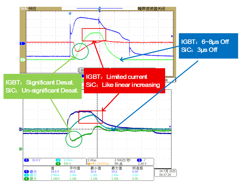
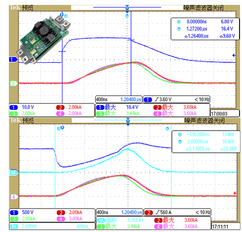
The following waveforms are extracted from actual testing. We can observe from the waveforms that when the module enters the desaturation state, the Vds voltage exhibits a noticeable upward movement before dropping to 0V. The lowest voltage point at this moment is the aforementioned Vds(desat). Waveforms without desaturation resemble the normal dual-pulse waveform.
Short-Circuit Protection Step 2: Execution
Upon detecting a short circuit, the protection sequence is immediately initiated. Signal logic varies among driver chips from different manufacturers. The figure below illustrates the typical protection sequence for the Firstack SiC driver:
- Fault Suppression Period (Suppression Time tBL): Following a short circuit, protection does not activate immediately but first enters an extremely brief suppression phase. This prevents potential current misjudgment during device turn-on, ensuring reliability.
- Fault Detection Period (RC Charging Time tRC): After suppression ends, the fault signal charges through an RC circuit. When its voltage reaches the set threshold VREF, a preliminary fault occurrence is confirmed.
- Fault Confirmation Period (Digital Filtering tDS_FLT): To eliminate false alarms caused by interference signals, the built-in digital filter in the driver chip performs a delayed confirmation. At this stage, the short-circuit fault is finally locked.
- Safe Shutdown Period (Soft Shutdown): After protection confirmation, the driver executes a soft shutdown (using high-resistance shutdown), gradually reducing the shutdown current to ensure the module safely exits its operational state.
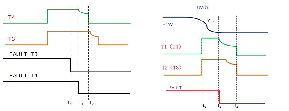
Compared to IGBTs, the core challenge in SiC short-circuit protection lies in achieving both “speed” and “stability.” By comparing the two short-circuit protection processes below, we can observe:
1. The short-circuit protection response time (approximately 1.5μs) and full turn-off time (< 3μs) of SiC are both significantly shorter than those of IGBT (4μs and 6-8μs, respectively). This necessitates that the drive circuit complete the entire process from fault detection to safe shutdown within an extremely limited time budget. This shift places the core focus of drive design on the precise coordination between filter time constants and detection voltage thresholds, where any improper configuration may lead to protection failure or false tripping.
2. Comparing the desaturation states of IGBT's Vce and SiC MOSFET's Vds reveals a key distinction: SiC exhibits a smaller variation in desaturation voltage. This narrows the voltage “window” for short-circuit detection, making accurate identification more challenging. Consequently, detection circuits require higher precision and resolution, with the core design objective being to precisely capture this faint fault signal without interfering with normal operation.
3. The short-circuit current characteristics of IGBTs and SiC differ significantly: the former rapidly enters a plateau phase, while the latter exhibits continuous linear growth within the protection window (theoretically reaching a peak before entering a decay phase, but by this point the module is already damaged, rendering protection meaningless). This difference results in significantly greater energy accumulation during short circuits for SiC, necessitating strict monitoring of its short-circuit withstand energy. The withstand capabilities of modules from different manufacturers vary greatly.
Short-Circuit Protection Testing: Test Platform
Short-circuit protection testing is inherently high-risk. Current SiC module manufacturing processes remain in development, with varying levels of tolerance, significantly increasing the probability of module failure (i.e., “module blowout”) during testing. Therefore, establishing a scientific, safe, and controllable testing process is critical. The primary step in conducting such tests is to safely and reliably simulate short-circuit faults under controlled conditions.
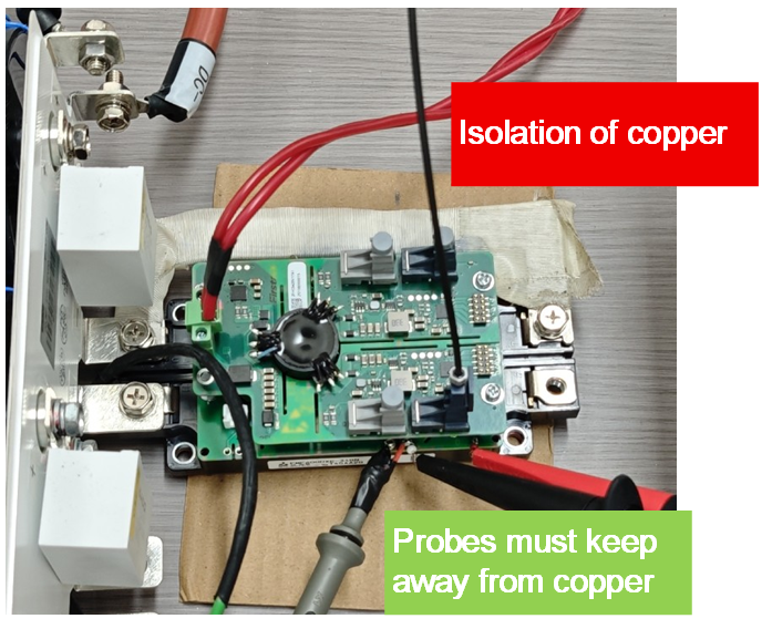
The most common short-circuit testing methods currently involve using shorting copper busbars/copper wires or simultaneously energizing both upper and lower tubes to create a direct path between bridge arms. As shown in the figure below, the DC and AC sides of the busbar in these two parallel test platforms are shorted via copper busbars. During testing, it is crucial to maintain a distance between the probe and the copper busbar to prevent interference from the high current flowing through the busbar. For practical testing, we recommend:
1. Apply insulation to copper to prevent unnecessary accidents.
2. Use ground loop probes (directly soldered to gate (G) and source (S)) or optically isolated probes for gate probes; other probes are highly susceptible to interference during testing.
3. Keep copper busbars/wires as short and thick as possible to minimize stray inductance, simulating a realistic Class I short-circuit environment.
In addition to the aforementioned copper busbar shorting method, another high-fidelity testing approach involves driving both upper and lower transistors to turn on simultaneously, thereby simulating the most realistic bridge arm short-circuit condition. This method precisely replicates Class I short circuits, with the core challenge lying in generating two fully synchronized and precisely controllable turn-on signals. To address this, the ME400D laboratory dynamic test equipment, independently developed by Firstack, provides an ideal solution. It not only effortlessly achieves precise upper and lower transistor simultaneous turn-on control but also elevates the efficiency of short-circuit protection testing and conventional dual-pulse testing to unprecedented levels, enabling fully automated testing and intelligent waveform analysis throughout the entire process.

The following waveforms are examples of three-parallel SiC short-circuit test waveforms we generated internally using the ME400D. The driver 2FHD0620, designed for the ED3 package, was employed. (Blue: Gate signal (top figure), Vds (bottom figure), remaining waveforms represent current)
Short-Circuit Protection Testing: Test Procedure
A key difference between SiC short-circuit testing and IGBT testing is the ability to start from low voltage. To ensure safety, the recommended standardized procedure is: First verify system functionality at 20V low voltage; then commence testing at 100V, incrementing voltage in 100V steps. Maintain a 5-10 minute interval after each test for module cooling and system recovery. If module failure or anomalies occur during testing, immediately disconnect power—never operate under high voltage.
Short-Circuit Protection Testing: Waveform Analysis
Next, we share some insights from Firstack's practical experience in analyzing waveforms during testing. First, we'll continue using the waveform mentioned earlier as our example. In short-circuit testing, beyond the well-known voltage and current values, what other details should we pay attention to?
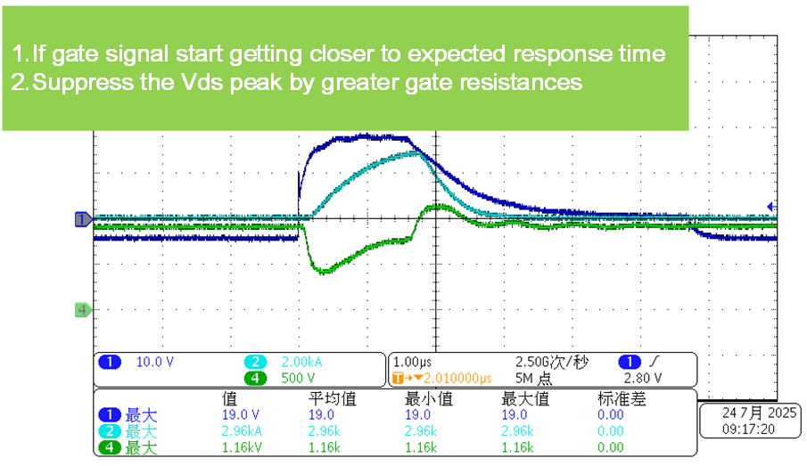
1. Not all SiC modules can reliably enter the desaturation state. For instance, when using a 1200V/300A module, testing often reveals that desaturation fails even at 400V or 500V. Continuing testing at higher voltages poses significant risks if desaturation still fails. In such cases, two measures can be taken to maximize safety:
- Compare gate waveforms: As the module approaches desaturation, the duration of the gate waveform increasingly aligns with the short-circuit protection response time. This can indicate whether the module is trending toward desaturation.
- Increase the turn-off resistor: Since the driver performs a hard turn-off before detecting desaturation, as long as the Vds spike does not exceed the module's withstand voltage, the overall short-circuit process incurs relatively low losses, minimizing the risk of module damage from overcurrent. This allows the bus voltage to be raised further for thorough module testing.
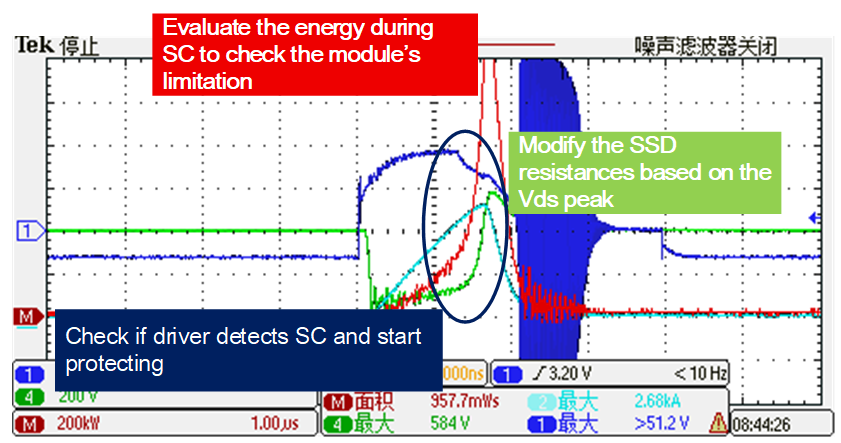
2.Not every test goes smoothly. If a transistor blowout occurs, we can still perform some analysis from the waveform. Take the waveform of this transistor blowout below as an example. Here, we need to focus on several critical points:
- The total energy during the short-circuit process before the blowout. This helps evaluate the module's short-circuit withstand capability.
- Whether the gate voltage and current begin to decrease during the blowout. A decrease indirectly confirms the driver's protection function is working properly. If not, it strongly suggests the driver signal is experiencing interference.
- The Vds voltage spike at this moment. This directly determines the value we select when adjusting the soft-shutdown resistor later. A smaller soft-shutdown resistor enables faster shutdown but may also cause excessively high Vds peaks.
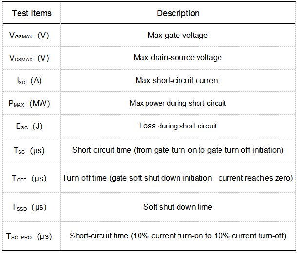
To verify the driver's short-circuit protection capability as thoroughly as possible, multiple data points must be recorded:
Summary
Short-circuit testing is undoubtedly a test of courage. No matter how much theoretical analysis is done, it ultimately comes down to testing on the bench. Especially after experiencing a blown tube, every test is done with bated breath. Here, I would also like to express my sincere admiration for all the engineers who perform short-circuit tests!